 817.465.9494
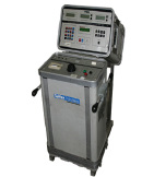
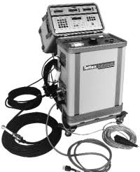
The Tettex 2816 Manual Power Factor Test Set is designed for onsite testing of high voltage distribution equipment
The rugged two piece design incorporates shock absorbing characteristics to facilitate transporting the instrument without affecting it’s precision.
Features:
- Digital displays
- Power loss direct or standardized to 10 kV
- Power Factor PF (cos ϕ)
- Dissipation factor (tan δ)
- Test current
- Test voltage
- Test frequency
- Capacitance
- Two measurement inputs to accommodate AN SI/ IEEE (UST, G ST and G STg) testing without changing connections
- Automatic interference suppression
- Built in printer
- Including RS 232C
- IEEE 488 output (optional)
- 200 mA, 12 kV AC power supply
- Automatic polarity reversal switch
- Manual voltage adjustment
- Measures while the voltage is being adjusted
- Fast setup and measuring
- Built in operator safety features
- Safety ground monitor circuit to ensure safe connections between the high voltage ground and earth ground before high voltage can be turned on. A light on the power supply indicates the ground status.
- Hand held safety push button switch
- Other parameters that can be selected for display – Apparent power
- Reactive power
- Inductance
- Quality factor
- Magnetizing current
- Iron loss current
- Built in standard capacitor
- Can be used with an external standard capacitor
- Operator entry of the number of measurements to be averaged
- Facilitates ratio entry for use with an external current comparator to extend the measuring range
- Simplified color coordinated operator input controls
- Retains last display and measuring mode setup when power is turned off
- Plain language error messages are displayed on a 2 line 16 character LC D display
- Permits entering up to seven ANSI temperature conversion tables to provide power factor printout standardized to 20 °C
- Automatic date and time on report print outs
- Operator entry of a test object identification number that will be printed on all reports
- A built in hardware self test sequence
- Field replaceable plug in printed circuit assemblies which are accessible from the front of the instrument
- Front panel mounted HV fuses and circuit breaker
Measured parameters:
Capacitance CX
at 200 mA, 50 Hz (60 Hz)
for 12 kV max. 53 nF (44 nF)
for 1 kV max. 630 nF (530 nF)
Resolution 0.01 pF
Limits of error ± 0.05 % rdg ± 1 dig
Inductance
Conditions 31 µA < IX < 200 mA
e.g. for 12 kV/50 Hz 190 H … 1273 kH
Resolution 0.1 mH
Limits of error ± 0.5 % rdg ± 2 dig
Dissipation factor (tan δ)
Range 0 … 9.99
Resolution 0.0001
Limits of error ± 1 % rdg ± 0.0001
Power factor PF (cos ϕ)
Range 0 … 1.00
Resolution 0.0001 Limits of error ± 1 % rdg ± 0.0001
Test voltage
Range 0 … 12.00 kV
Optional 0 … 2.00 kV
Resolution 0.001 kV
Limits of error ± 1.0 % rdg ± 2 dig
Test current
Range 0 … 15.00 A
Resolution 0.001 mA
Limits of error ± 1.0 % rdg ± 2 dig
Test frequency
Range 45.00 … 65.00 Hz
Resolution 0.01 Hz
Limits of error ± 0.02 % rdg
Quality factor
Range 0.1 … 9999
Measuring time
First reading 4 sec
Update readings 0.6 sec intervals
Display range of other parameters
Apparent power (S) 0 mVA … 999.9 kVA
Actual power (P) 0 mW … 999.9 kW Reactive power (Q) 0 mVAr … 999.9 kVAr
Magnetizing current (Im) 0 … 999.9 A
Iron loss current (Ife) 0 … 999.9 A
Standard capacitor
Internal ≈100 pF / 12 kV max.
Test current limitations
C N : The external capacitor input current range is limited to greater than 31 µA and less than 15 mA.
C X: A and B test object capacitances are limited to 15 A maximum.
High voltage output
The high voltage section has a dual range (12 kV) manual voltage adjustment:
Voltage 0.1 kV … 12 kV
Current 200 mA (continuous)
Optional range:
Voltage 0 … 2 kV
Current 5 mA
Stated error is based on the following test conditions
Standard capacitor CN = 100 pF
Test voltage ≥ 1000 V
Unknown capacitance 50 · C N < C X < 2000 · C N 31 µA < IX < 15 A
The ranges shown are limited by the power supply limits of 200 mA, 12 kV. For ranges of the 2816 with external standard refer to the “range extension” section of this specification.
Operating temperature
5 °C to + 40 °C
Mains supply
Voltage 230 V or 115 V ± 10%
Current (no load) 180 mA / 360 mA
(full load) 11 A / 22 A
Frequency 50/ 60 Hz
Weights and dimensions
Two interlocked stacking cases
(W x H x D) 500 x 310 x 470 mm
(20.8 x 12.8 x 24.2 in) each
– Measuring instrument 40 kg (88 Ib)
– HV-transformer/control with support bracket 86 kg (189 Ib)
– Case with cables 24 kg (53 Ib)
Applicable standards
The measuring system is designed in accordance with the appropriate sections of the following specifications:
– ANSI / IEEE C 57.12.90
– VDE 0411/Part 1
– IEC 348 / Safety category I
– IEC 359
Reviews
There are no reviews yet.